



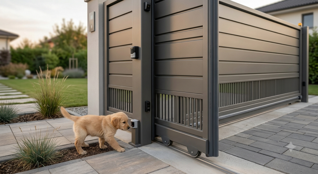
Integrating automation systems into contemporary residences primarily serves two fundamental needs: living comfort and perimeter protection. However, when pets are present within domestic or condominium spaces, the automation project takes on a broader dimension. Dogs and cats regard the garden and access areas as direct extensions of their living territory. Consequently, the passage interface to the outside—represented by sliding or swing gates—must be designed to eliminate any mechanical or electronic risk factors.
For designers, installers, and property owners, securing an automated entrance requires an in-depth understanding of leaf movement dynamics, obstacle detection systems, and current technical regulations. An offhand approach can turn a convenient feature into a source of danger, with risks ranging from entrapment and crushing to accidental pet escape onto the roadway.
In this technical breakdown, we will analyze the engineering strategies, regulatory protocols, and hardware solutions designed to create gate and entrance automation systems that combine high operational safety standards with constant protection for pets.
[ MECHANICAL RISK ZONE ] │ ┌────────────────┼───────────────┐
│ ▼ ▼ ▼
Crushing Impact Shearing /(Leaf Closing)
(Movement) Trapping (Sliding)
Primary Crushing Risk
This occurs during the final closing phase of the gate, whether swing or sliding.
- In swing gates: The critical point is the closure space between the main leaf and the stop post, or between the two leaves as they approach each other. A small dog or cat attempting to cross the gap in the final centimeters of travel risks facing significant impact and crushing forces.
- In sliding gates: The frontal impact point between the leading edge of the leaf and the fixed stop represents a high-pressure area if force limitation or reversal systems are not properly calibrated.
Shearing and Dragging Risk
A danger typical of sliding gates. It develops in the area between the bars of the moving leaf frame and the support pillars or guide strips.
- If a pet inserts its head or paws between the vertical bars of the gate while it is moving, the movement of the leaf against the fixed structure can cause severe shearing injuries.
- Ground drive wheels and upper guide rollers represent additional pinching points for paws, tails, or long coats.
Entrapment and Escape Risk
Beyond direct physical harm caused by moving parts, there is a structural risk linked to the gate’s configuration:
- Excessive ground clearance: A pronounced gap between the bottom edge of the gate and the paving allows cats or very small dogs to crawl underneath, accessing the street even when the gate is fully closed.
- Extended automatic closing delay: An overly long pause between opening and subsequent automatic reclosing leaves a wide window of time for a pet to wander off unnoticed.
2. European Regulatory Framework and Protection for Vulnerable Users
Gate automations are classified at the European level as “machinery” and fall under the scope of the Machinery Directive 2006/42/EC, alongside the product standard EN 13241-1. When designing a system, the specifications analyzed to ensure pet safety coincide with those established for protecting “vulnerable users” (children, the elderly, and individuals with reduced mobility).
EN 12453 Standard: Measuring Impact Forces
The EN 12453 standard defines safety requirements related to the use of motorized gates, specifying the maximum allowable impact force limits during leaf movement. The standard mandates that dynamic impact force must be reduced within extremely rapid timeframes and that residual static force must remain within well-defined safety curves.
To achieve compliance and safeguard the animal, the system must integrate one of the following systems or a combination thereof:
- Force limitation via control unit and encoder: The automation detects an increase in motor strain caused by an obstacle and immediately reverses the direction of travel.
- Supplementary protective devices (PS): The use of photocells, sensitive edges (safety edges), and optical scanners positioned at key points on the frame.
3. Active Protective Devices: Photocells and Infrared Barriers
Accident prevention relies on a fundamental rule: prevent physical contact before it can occur. Photocells represent the primary active safety feature within an automated entrance.
The Limitation of Standard Configurations
A traditional installation includes a single pair of photocells placed at a height of 40 to 60 centimeters above the ground. While this height is suitable for detecting human figures or motor vehicles, it leaves severe coverage gaps when pets are present:
- A small dog (such as a Dachshund or Pomeranian) or a cat passes beneath the infrared beam without interrupting it.
- The control unit, detecting no obstacle, proceeds to close the gate.
The Dual-Level Beam Solution
To fully shield the passage, photocells should be installed at two differentiated height levels:
|
Device Type |
Height Above Ground |
Operational Purpose |
|
Low Photocell |
15 – 20 cm |
Detection of small to medium pets, puppies, and ground-level obstacles. |
|
High Photocell |
50 – 60 cm |
Detection of vehicles, pedestrians, and large dogs. |
Synchronized Photocells and Adjustable Optics
In settings with limited space or complex geometries, using synchronized photocells prevents cross-talk interference between transmitted beams. Additionally, adjustable optics allow precise alignment of the beam even on irregular surfaces or misaligned pillars, ensuring a constant signal free from false alarms caused by vegetation.
4. Sensitive Protective Devices: Mechanical and Resistive Safety Edges
Should a pet bypass the optical barrier of the photocells, system safety relies on contact-sensitive devices, known as safety edges or sensitive edges.
Mechanical vs. 8.2 kΩ Resistive Edges
- Mechanical microswitch edges: Operate via an internal tensioned cable that opens an electrical contact when the rubber profile is compressed. They require a higher deformation force before activation.
- 2 kΩ resistive edges: Represent the state of the art for pet protection. The soft EPDM rubber profile contains an internal conductive element whose resistance is continuously monitored by the control unit. Minimal deformation caused by contact with a pet’s body alters the ohmic value, causing the motor to stop and reverse instantly before crushing forces reach dangerous levels.
Strategic Placement on Gates
- Sliding Gates:
- On the leading edge of the moving leaf (protection against frontal impact).
- On fixed closing and opening stops.
- On the bottom edge of the leaf if ground clearance varies along the path.
- Swing Gates:
- On the outer vertical edges of the leaves.
- In the rear sweep area between the opening leaf and the enclosure wall, where a pet could become trapped.
5. Intelligent Motion Control: Control Units, Encoders, and Low-Voltage Motors
The mechanical and electronic components of the automation system must communicate in real time through advanced control units. Motor technology and power delivery management form the structural core of dynamic safety.
Advantages of 24V DC Motors
Motors powered by 24V direct current offer far superior performance compared to traditional 230V AC motors regarding dynamic safety, due to:
- Speed Modulation (Deceleration): They allow precise control of approach speeds in the final centimeters of travel, reducing leaf inertia.
- Obstacle Reactivity: Combining 24V motors with smart control boards allows continuous monitoring of current draw. An unexpected spike in current (caused by the leaf pressing against a pet) triggers an immediate stop and direction reversal in fractions of a second.
Management via Encoder
An encoder is a kinematic sensor that tracks the exact position and travel speed of the leaf millimeter by millimeter.
- If the gate encounters minimal resistance (such as the body of a small pet) that does not yet trigger the primary current-sensing threshold, the encoder detects the imperceptible speed change in the motor shaft.
- The signal is sent to the motherboard, which activates safeguard maneuvers, reducing residual impact forces to zero.
6. Gate Fabrication and Frame Design: Eliminating Structural Traps
No automation, no matter how advanced, can fully compensate for structural flaws in the metal framework. Pet safety requires a combined analysis of the gate leaf and the motorization system.
Rules for Framework and Installation
- Vertical Bar Spacing:
- In palisade or tubular gates, bar spacing greater than 50 mm poses a head-entrapment risk for small to medium dogs.
- Solution: Install a fine-mesh stainless steel screen, laser-cut sheet metal, or polycortene panels along the lower section of the gate (up to a height of at least 80–100 cm).
- Ground Clearance (Gap Between Bottom Edge and Paving):
- The lower edge of the gate must maintain a consistent distance from the ground no greater than 30–40 mm throughout its full opening or sliding path.
- If the ground slants, dense brush seals or deformable bottom safety edges must be installed to prevent animals from squeezing beneath the leaf.
- Rack and Transmission Components in Sliding Gates:
- Drive racks mounted on the leaf must feature protective covers to prevent a pet’s fur or tail from getting caught in the rotating motor pinion.
- Guide Roller Covers:
- Upper guide rollers on sliding leaves must be enclosed within anti-pinching guards compliant with the EN 12604 standard.
7. Advanced Features and Logic Controls for Pet Management
Modern VDS Automazioni control units allow the programming of dedicated operating modes to minimize the risk of pets escaping or entering hazardous situations.
Adjustable “Pedestrian Opening” Logic
Pedestrian opening activates the movement of a single leaf (in swing gates) or limits leaf travel to a preset width (e.g., 90–100 cm in sliding gates).
- Using pedestrian opening for human foot traffic reduces the open gap and overall cycle duration.
- This prevents large dogs from taking advantage of extended vehicular transit times to run outside.
Rapid Closure After Transit (“Photo-Close” Logic)
Enabling the Photo-Close (or Fast Closing) function on the control board instructs the system not to wait for the full programmed pause time. Instead, it initiates reclosing a few seconds after a vehicle interrupts and clears the photocell beam.
- This configuration minimizes the window of time during which the entrance remains unattended.
Integration with Smart Home and Access Control Systems
Integrating Wi-Fi or Bluetooth modules into the electronic boards allows remote monitoring of entrance status via smartphone:
- Open Gate Notification: Sends a visual or audible alert to the phone if the gate is left open in manual mode or due to a mechanical blockage, preventing pets from leaving unnoticed.
- Geofencing Controls: Automatic opening based on smartphone GPS location should be carefully calibrated to avoid unintended openings when the owner is near the property line without intending to enter, which could leave an escape path open for pets in the yard.
8. Periodic Maintenance Protocol for Paw-Proof Installations
A system that is safe upon installation must maintain its performance over time. The presence of pets demands frequent inspections, as fur, dirt, waste, or chewed wiring can compromise sensor functionality.
Inspection Checklist for Users and Technicians
- Photocell Cleaning:
- Regularly clean the protective lenses of low-mounted photocells (15–20 cm). Being close to the ground, they easily collect mud, grass clippings, cobwebs, or loose fur.
- Visual Cable and Edge Inspection:
- Ensure puppies or pets have not chewed through the rubber covers of sensitive edges or exposed wiring near support pillars.
- Impact Stop Testing:
- Place a soft obstacle (such as a dense foam block or impact simulator) at various heights along the gate path to verify that direction reversal occurs instantaneously and smoothly.
- Sliding Track Maintenance:
- Clear leaves, stones, or small debris lodged in the ground track of sliding gates. Fixed obstacles can trigger false motor reversals or cause dangerous leaf misalignments.
9. VDS Automazioni Safety Solutions Comparison Matrix
To assist in choosing the most suitable components during the design or retrofit phase, the following matrix summarizes applicable technologies:
|
Protective Technology |
Covered Risk Level |
Effectiveness for Small Pets (<10 kg) |
Effectiveness for Large Pets (>25 kg) |
Impact on Gate Aesthetics |
|
Single Photocell (50 cm) |
Vehicle / Pedestrian impact |
** Low ** (Undershoot risk) |
** Medium ** |
Minimal |
|
Dual Photocell (15 cm + 50 cm) |
Entrance obstruction prior to motion |
** High ** |
** Excellent ** |
Minimal |
|
8.2 kΩ Resistive Edge |
Crushing / Direct contact |
** Excellent ** (Triggers on light pressure) |
** Excellent ** |
Low (Profile along edge) |
|
24V Motor with Encoder |
Dynamic impact force |
** High ** (Prevents severe crushing) |
** High ** |
None (Built into operator) |
|
Framework Mesh Guard |
Head trapping / Free passage |
** Excellent ** (Physical barrier) |
** Excellent ** |
Medium (Requires design integration) |
10. Installation Checklist for Retrofitting Existing Systems
To upgrade an existing automation system for pet safety, follow this step-by-step retrofitting checklist:
- [ ] Step 1: Measure ground clearance and structural gaps
- Ensure there are no gaps greater than 4 cm between the lower edge of the gate and the ground.
- If larger gaps exist, install high-density brush seals or metal/polymer extension panels.
- [ ] Step 2: Add low-level photocells
- Mount a second pair of photocells at a height of 15 to 20 cm from the ground.
- Connect the contacts in series or to the dedicated inputs on the control board.
- [ ] Step 3: Fit resistive safety edges on impact zones
- Install 8.2 kΩ sensitive edges on the leading edge of sliding gates and the closing stops of swing gates.
- [ ] Step 4: Reconfigure control unit logic
- Set automatic reclosing pause times to shorter durations.
- Enable deceleration features during the final centimeters of travel (soft-stop).
- Program pedestrian opening to the minimum distance required for foot traffic.
- [ ] Step 5: Final testing and impact force verification
- Perform impact force measurements using a force gauge in compliance with EN 12453, ensuring values fall safely within limits established for vulnerable users.
Conclusion
Creating a safe entry and exit point for pets involves more than just fulfilling legal regulatory requirements; it requires a conscious, safety-first design approach. Combining well-structured gate framework, 24V DC motor technology with encoder feedback, and targeted multi-level safety sensors (low photocells and resistive edges) virtually eliminates operational risks.
These safety upgrades allow homeowners to enjoy their outdoor spaces with complete peace of mind, knowing that gate operations remain safe and protective for four-legged companions at all times.